
Lock-in Thermography Composite Inspection: Detecting Hidden Carbon Fiber Damage
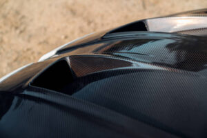
Carbon fiber reinforced polymer (CFRP) automotive components can sustain serious internal damage without showing obvious surface deformation. A hood, roof panel, or aerodynamic diffuser may retain a smooth clear coat after a hailstone or road-debris impact, even when internal composite layers have separated.
This condition is known as Barely Visible Impact Damage (BVID). For automotive procurement managers, Tier-1 suppliers, and quality assurance engineers, BVID creates a significant inspection challenge: a visually acceptable component may still contain subsurface defects that affect structural performance.
Lock-in thermography composite inspection provides a non-destructive testing (NDT) method for evaluating hidden defects by analyzing how heat moves through a composite structure. When combined with appropriate inspection procedures and acceptance criteria, active thermography can help manufacturers identify potential delamination before damaged parts enter the supply chain.
This guide explains why visual inspection alone is insufficient for carbon fiber components, how lock-in thermography detects subsurface damage, and what B2B buyers should include in their composite quality control requirements.
1. What Is Barely Visible Impact Damage (BVID) in Carbon Fiber Composites?
BVID occurs when an impact causes internal damage to a composite component that is difficult to identify through ordinary visual inspection.
Unlike many metallic panels, CFRP structures may not retain a pronounced dent after impact. The surface can recover its apparent shape while the internal structure experiences matrix cracking, interlaminar separation, or other damage.
Why can carbon fiber parts look undamaged after impact?
CFRP combines reinforcing carbon fibers with a polymer matrix. Its response to impact depends on factors such as laminate architecture, resin properties, impact energy, panel thickness, and boundary conditions.
An impact can create several types of internal damage:
- Matrix cracking: Cracks form in the polymer matrix surrounding the reinforcing fibers.
- Interlaminar delamination: Adjacent composite plies separate, creating a discontinuity within the laminate.
- Fiber damage: Individual fibers or fiber bundles may fracture or lose load-carrying capability.
- Combined internal damage: Multiple damage mechanisms may occur together, even when the external surface appears relatively intact.
These defects can reduce local stiffness or strength and may affect fatigue performance under repeated loading. The actual structural consequences depend on the component design, damage location, and loading conditions.
For procurement teams, the critical point is straightforward: a smooth surface does not prove that a carbon fiber component is structurally defect-free.
2. Metal Panels vs. CFRP: Why Visual Inspection Has Different Limitations
Conventional automotive steel and aluminum panels often retain visible dents, bending, or paint damage after an impact. Composite structures can behave differently, making subsurface inspection more important.
| Inspection factor | Automotive steel and aluminum | Carbon fiber reinforced polymer (CFRP) |
|---|---|---|
| Typical impact response | May exhibit plastic deformation, denting, or bending | May experience matrix cracking, delamination, or fiber damage |
| Visible surface indication | Surface deformation may reveal impact damage | Internal damage may exist with little visible surface change |
| Potential hidden defects | Subsurface defects can also occur in metals | Interlaminar separation and matrix damage can be difficult to see |
| Role of visual inspection | Useful for detecting surface deformation and finish defects | Essential as an initial check, but insufficient for ruling out BVID |
| Additional inspection methods | Methods selected according to the suspected defect | Ultrasonic testing, active thermography, and other suitable NDT methods |
Visual inspection remains important for both materials. However, composite quality control often requires additional methods capable of detecting defects beneath the visible surface.
The original article cites a visual-inspection detection rate below 15% for impact-induced composite failures. This figure should not be treated as a universal performance benchmark without a defined dataset, defect population, and inspection protocol. Actual detection capability varies with damage type, size, depth, lighting, surface condition, and inspector training.
3. How Lock-in Thermography Composite Inspection Works
Lock-in thermography is an active thermographic NDT technique. It applies periodically modulated thermal energy to a component and measures the resulting surface temperature response with an infrared camera.
Subsurface defects can alter heat transfer through the material. By analyzing the thermal response, inspectors can identify areas that behave differently from sound composite regions.
Step 1: Apply modulated thermal energy
A controlled heat source, such as a periodically modulated lamp, delivers thermal energy to the surface of the carbon fiber panel.
The heat travels through the composite by conduction. The inspection system repeats the heating cycle at a defined modulation frequency to produce a measurable periodic thermal response.
Step 2: Detect changes in heat transfer
A delamination or other internal discontinuity can introduce additional thermal resistance. This changes how heat moves through the laminate and may alter the surface temperature response above the defect.
The thermal contrast depends on factors such as defect depth, size, orientation, material properties, and inspection settings. Not every internal defect produces a detectable thermal signal.
Step 3: Capture the thermal response with an infrared camera
An infrared camera records the surface temperature variation during repeated heating cycles.
Rather than relying only on a single temperature image, lock-in thermography analyzes the periodic response over time. This can improve the visibility of certain subsurface defects against background variations.
Step 4: Process phase and amplitude data
Thermography software extracts parameters such as phase and amplitude from the measured thermal signal.
- Phase images describe the timing relationship between the applied heating cycle and the measured surface response.
- Amplitude images describe the magnitude of the periodic temperature variation.
Defects can appear as thermal contrasts in these processed images. Phase analysis can be useful when surface emissivity variations or uneven heating affect raw temperature measurements, although performance depends on the inspection setup and material.
Step 5: Evaluate and document indications
Inspectors review the thermal images and determine whether detected indications require further evaluation. Depending on the application, follow-up inspection may involve ultrasonic testing or another suitable NDT technique.
The final assessment should compare the findings with defined acceptance criteria rather than interpreting every thermal contrast as a confirmed delamination.
4. Lock-in Thermography vs. Ultrasonic C-Scan for CFRP Inspection
Lock-in thermography is not the only method available for detecting internal defects in carbon fiber components. Ultrasonic testing, particularly C-scan inspection, is also widely used for composite evaluation.
The appropriate method depends on the component geometry, laminate construction, defect type, inspection access, required sensitivity, and production environment.
| Evaluation factor | Lock-in thermography | Ultrasonic C-scan |
|---|---|---|
| Detection principle | Measures surface thermal response to modulated heating | Measures ultrasonic signal transmission or reflection through the material |
| Inspection approach | Non-contact surface heating and infrared imaging | Ultrasonic scanning, commonly with a suitable probe and coupling arrangement |
| Typical output | Thermal phase and amplitude maps | Spatial maps of ultrasonic responses and indications |
| Potential advantages | Non-contact inspection and rapid coverage of suitable surfaces | Detailed internal evaluation when the material and inspection setup provide suitable acoustic access |
| Main limitations | Sensitivity depends on defect depth, size, thermal properties, and heating conditions | Results depend on acoustic coupling, geometry, attenuation, laminate structure, and probe configuration |
| Suitable role | Screening or evaluating defects that produce measurable thermal contrast | Evaluating internal discontinuities using an appropriate ultrasonic procedure |
These methods are complementary rather than universally interchangeable. A qualified inspection plan should select the method—or combination of methods—that can reliably detect the defect types relevant to the component.
For critical structural parts, procurement teams should ask suppliers to explain the selected NDT method, its demonstrated capability, and the applicable acceptance criteria.

5. How to Build a Reliable Composite NDT Acceptance Process
For B2B buyers, the objective is not simply to request an inspection certificate. The objective is to ensure that the inspection procedure matches the component’s actual risks and contractual requirements.
1. Define the component and critical inspection areas
Identify the component model, laminate construction, thickness, geometry, and locations that require inspection. Areas exposed to impact, concentrated loading, or demanding aerodynamic conditions may warrant particular attention.
2. Specify the relevant defect types
Define which defects the inspection must detect, including delamination, matrix cracking, or other damage relevant to the part’s design.
Do not assume that one NDT method has the same sensitivity to every defect type.
3. Select a qualified inspection method
Evaluate whether lock-in thermography, ultrasonic C-scan, or a combination of techniques is appropriate.
The inspection procedure should specify the equipment, test conditions, coverage, calibration or reference standards, and method used to assess indications.
4. Establish acceptance criteria before production
Agree on how indications will be evaluated. Depending on the component and engineering requirements, criteria may address indication size, location, depth, allowable defect population, or the need for further inspection.
Acceptance limits should come from the component design authority, applicable specifications, or an approved engineering procedure—not from a generic visual judgment.
5. Require traceable inspection documentation
For structural composite components, procurement specifications can require relevant NDT records for each defined batch or shipment.
A useful report may include:
- Part number, revision, and component identification.
- Batch or serial number and inspection date.
- Inspection method and procedure revision.
- Equipment identification and relevant test settings.
- Inspection coverage and any inaccessible areas.
- Thermal images or ultrasonic C-scan data, where applicable.
- Recorded indications and their evaluation.
- Acceptance status and inspector authorization.
- Details of any additional testing or disposition.
Where the purchase contract or regulatory framework requires accredited inspection or a specific certification, state that requirement explicitly. An NDT report should not be described as an accredited certificate unless the issuing organization and the scope of accreditation support that claim.
6. B2B Quality Control FAQs for Carbon Fiber Components
How can procurement inspectors identify internal damage in an incoming carbon fiber part?
Start with visual inspection, then use a suitable NDT method when the component’s risk profile requires subsurface evaluation. Lock-in thermography and ultrasonic C-scan can identify different classes of internal indications, depending on the material and inspection procedure.
For safety-critical or highly loaded components, follow the approved inspection plan rather than relying on appearance alone.
What percentage of composite impact damage can visual inspection detect?
There is no single detection percentage that applies to every CFRP component and inspection environment. Visual inspection may miss internal delamination when the surface shows little or no deformation.
Detection rates depend on the defect population, inspection conditions, surface finish, inspector training, and the definition of a successful detection. Any numerical claim should be supported by a clearly defined validation study.
Can a supplier claim that a carbon fiber part is defect-free because its clear coat is smooth?
No. A smooth clear coat demonstrates surface appearance, not the absence of internal damage.
The part may require additional inspection based on its intended function, impact history, design criticality, and contractual quality requirements. A suitable NDT procedure provides stronger evidence than visual appearance alone.
Can lock-in thermography determine the exact depth and severity of every delamination?
Not in every case. Thermography can reveal thermal indications associated with subsurface defects, but the ability to estimate depth or defect severity depends on the method, equipment, material, and validation procedure.
Where precise characterization is required, additional evaluation—such as ultrasonic testing or a validated engineering assessment—may be necessary.
Should every incoming carbon fiber component receive thermography inspection?
The inspection scope should be risk-based and aligned with the component specification, supplier quality plan, and applicable engineering requirements. Critical structural parts may require defined NDT coverage, while other components may follow a different validated inspection plan.
The important requirement is to specify the inspection method and acceptance criteria before production or delivery, rather than relying on an informal visual sign-off.
7. Key Takeaways for Carbon Fiber Procurement and Quality Teams
- Do not rely on surface appearance alone: BVID can leave a CFRP component looking intact while internal damage remains.
- Use NDT according to the defect risk: Lock-in thermography and ultrasonic C-scan provide complementary ways to investigate subsurface composite damage.
- Understand the detection mechanism: Thermography identifies changes in heat transfer, while ultrasonic testing evaluates acoustic responses.
- Set acceptance criteria in advance: Define the relevant defect types, inspection coverage, and disposition rules before supplier production.
- Request traceable reports: Ensure that NDT records identify the part, inspection method, findings, and acceptance decision.
- Validate inspection capability: Confirm that the selected method is suitable for the actual laminate, component geometry, and required defect sensitivity.
Conclusion: Make NDT Part of Carbon Fiber Component Acceptance
Barely Visible Impact Damage creates a challenge for automotive carbon fiber quality control because a component can retain a smooth exterior while sustaining internal composite damage.
Lock-in thermography composite inspection helps address this challenge by analyzing how modulated heat moves through the laminate and identifying thermal indications associated with subsurface discontinuities. Ultrasonic C-scan and other suitable NDT methods can provide complementary information when the application requires it.
For procurement managers and quality engineers, the most effective approach combines risk-based inspection, validated testing procedures, defined acceptance criteria, and traceable supplier documentation. This process helps teams make more informed decisions about incoming CFRP components and reduces reliance on visual appearance as the sole measure of structural integrity.





Leave a reply